Why Your Vacuum Lifter Lost Suction: A Step-by-Step Diagnostic Flowchart
Losing suction on a vacuum lifter is more than an inconvenience—it’s a safety hazard and a productivity killer. Whether you’re handling fragile glass panes, heavy carbon steel plates, or polished stainless steel sheets, a sudden loss of vacuum can lead to dropped loads, damaged materials, and serious workplace injuries. Understanding why your vacuum lifter failed is the first step toward preventing recurrence and restoring safe, efficient operation.
In this comprehensive guide, we’ll walk you through a systematic diagnostic flowchart designed for all major types of vacuum lifters, including glass vacuum lifters, sheet metal vacuum lifters, vacuum tube lifters, and systems used for carbon steel, aluminum plate lifting, and stainless steel sheet handling. You’ll learn how to pinpoint the root cause of suction loss—from simple seal leaks to complex pump failures—and implement the right fix quickly.Download our free vacuum lifter technical scheme at the end to get a ready-to-use troubleshooting checklist and maintenance log.
Understanding How Vacuum Lifters Work
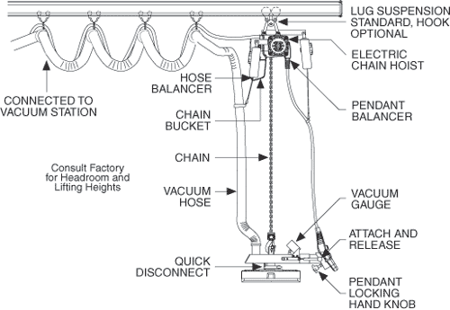
Before diving into diagnostics, it’s essential to grasp the basic mechanics. A vacuum lifter uses a vacuum pump or venturi system to remove air from between the suction cups (or pads) and the load surface. The resulting pressure difference creates a holding force strong enough to lift and move materials safely. The system relies on three critical elements:
- Vacuum generation – the pump or ejector that creates negative pressure.
- Sealing interface – the suction cups or pads that conform to the load surface.
- Load surface quality – the material’s smoothness, cleanliness, and porosity.
Any failure in one of these areas can cause a partial or complete loss of suction. The diagnostic flowchart below addresses each component in a logical order, helping you move from simple, high-probability causes to more complex internal faults.

Common Causes of Vacuum Lifter Suction Loss
Suction loss rarely happens without warning. Typical symptoms include:
- The load slips or drifts during lifting.
- The vacuum gauge shows a slow pressure drop.
- The lifter’s alarm sounds (if equipped).
- The suction cups fail to attach to the load at all.
- The pump runs continuously without achieving target vacuum.
The most frequent culprits include:
- Worn or damaged suction cups – cracks, tears, hardening, or flattening.
- Clogged vacuum filters or lines – dust, rust, oil, or debris.
- Leaking fittings, hoses, or valves – age, vibration, or improper assembly.
- Contaminated load surfaces – oil, rust, scale, moisture, or dust.
- Inadequate pump performance – worn vanes, low oil, or overheating.
- Oversized or undersized cups for the load – incorrect configuration.
- Bypassed or malfunctioning safety check valves – especially in multi-cup systems.
Each of these will be addressed in the flowchart below.
Diagnostic Flowchart: Step-by-Step Suction Loss Troubleshooting
Follow this sequence from Step 1 to Step 8. At each step, you’ll either identify the fault or rule out a common cause, allowing you to move deeper into the system.

Step 1: Verify Power Source and Pump Operation
Question: Is the vacuum pump running at all?
- No pump sound / motor not starting → Check electrical supply, fuses, emergency stops, and control relays. For pneumatic venturi systems, verify compressed air supply (minimum 5–6 bar typically).
- Pump runs but sounds weak or labored → Inspect oil level (for rotary vane pumps), air filter (for venturi), and listen for unusual noise indicating vane wear or bearing failure.
- Pump runs normally → Proceed to Step 2.
Key Insight: A pump that runs but fails to pull vacuum often indicates internal wear or a massive leak somewhere in the system. Don’t assume the pump is healthy just because it’s spinning.
Step 2: Check Vacuum Gauge and Target Level
Question: Does the vacuum gauge reach the manufacturer’s recommended level (typically -0.6 to -0.8 bar / 60–80% vacuum)?
- Gauge never moves → Suspect a completely open line, missing cup, or a gauge that is itself faulty. Test gauge with a known good vacuum source.
- Gauge rises slowly but plateaus below target → This points to a partial leak, undersized pump, or too many open cups. Check for closed but leaking valves.
- Gauge reaches target then drops when load is applied → The system cannot maintain vacuum under load—likely a seal leakage or cup deformation issue. Proceed to Step 3.
Material-Specific Note: For porous loads like unpolished carbon steel with heavy rust, achieving full vacuum may be impossible if the surface is too rough. The vacuum gauge will reflect the system’s capability, not the load’s suitability.
Step 3: Inspect Suction Cups and Pads
Question: Are the suction cups in good condition and correctly matched to the material?
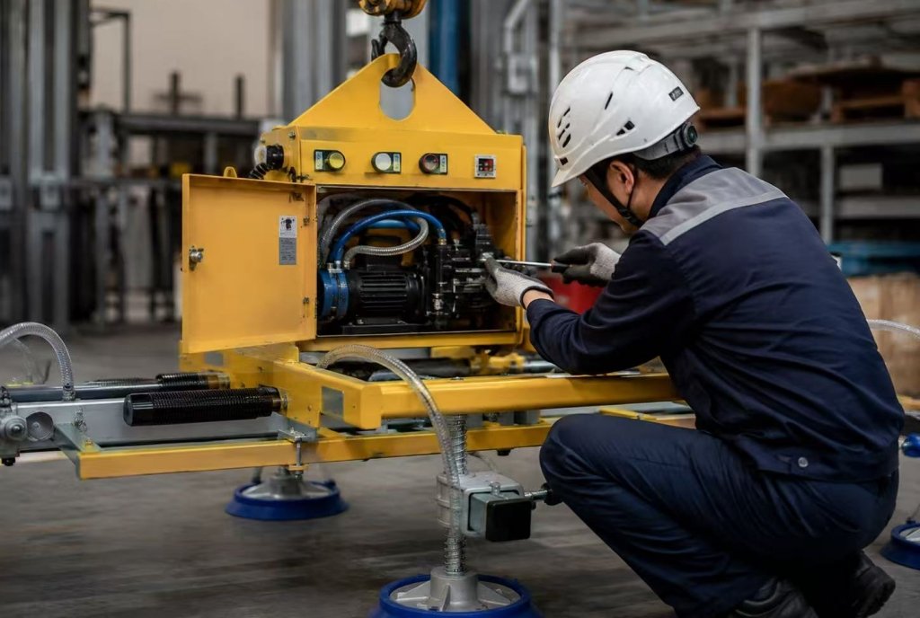
- Visual inspection – Look for cracks, tears, deformation, hardening, or embedded debris. Replace any cup that shows wear.
- Flexibility test – Squeeze the cup lip; it should be pliable and spring back. Hardened cups lose conformability and leak.
- Size and shape – For flat glass, use flat oval or round cups. For corrugated or rough sheet metal, use deep bellows cups. For stainless steel sheets with oil film, use cups with oil-resistant rubber (e.g., nitrile, polyurethane).
- Cup mounting – Ensure cups are securely attached to the lifter frame; loose bolts cause misalignment and uneven sealing.
Common Mistake: Using the same cups for all materials. A glass vacuum lifter cup may be too stiff for thin aluminum plate, leading to edge leakage. A sheet metal vacuum lifter cup may be too soft for heavy carbon steel, causing excessive deformation and premature failure.
Step 4: Evaluate Load Surface Condition
Question: Is the load surface clean, dry, and smooth enough for the cups to seal?
This is the most overlooked cause of suction loss. Different materials present unique challenges:
- Glass – Must be free of dust, film, or condensation. Even a thin layer of moisture can dramatically reduce friction and allow sliding. Use clean, dry cups rated for glass.
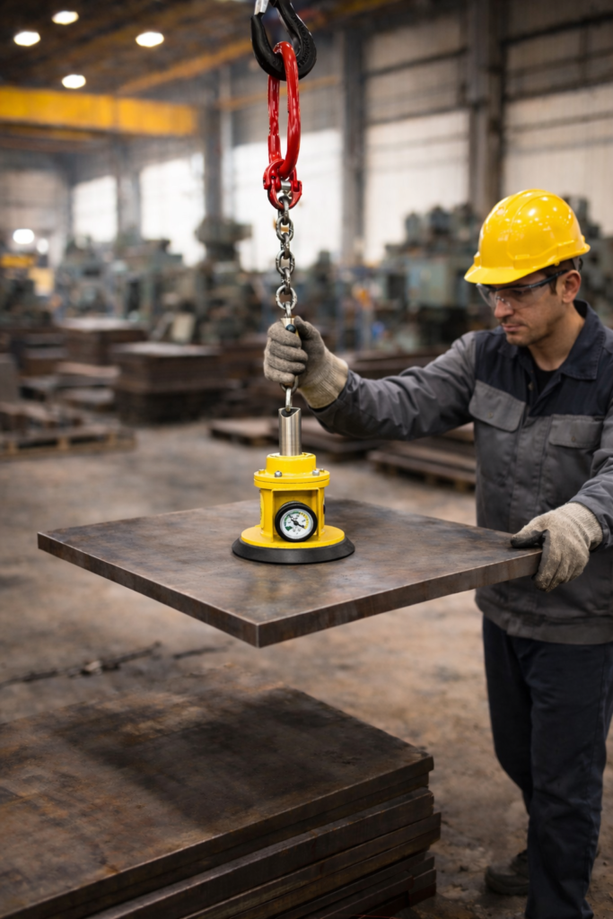
- Carbon Steel – Often coated with mill scale, rust, or protective oil. Mill scale is porous and abrasive; oil reduces friction and can degrade cup material. Clean the surface or use cups with high oil resistance and rough-surface capability.
- Aluminum Plate – Frequently has an oxidized layer that is rough and porous. Also, aluminum is softer and may deform under high vacuum if the cup area is too small, causing local collapse. Ensure cups are sized correctly.
- Stainless Steel Sheet – Usually smooth and non-porous, but may have a plastic protective film or a light oil coating from the mill. Remove the film before lifting, or the cup will seal to the film only and peel it off.
Action: Wipe the test area with a clean, dry cloth. Retry lifting. If suction improves, the problem was surface contamination. Implement a cleaning protocol before lifting.
Step 5: Check for Vacuum Leaks in Lines, Fittings, and Valves
Question: Is the vacuum system airtight? Even tiny leaks can prevent reaching full vacuum.
- Audible leaks – Listen for hissing sounds while the pump runs under load.
- Soapy water test – Apply soapy water to all fittings, hose connections, valve stems, and pump seals. Bubbles indicate a leak.
- Vacuum decay test – With the lifter attached to a clean, non-porous test plate, pump down to target vacuum, close the isolation valve (if present), and turn off the pump. Watch the gauge. A pressure rise of more than 10% within 60 seconds indicates a significant leak.
- Check valves – In multi-cup systems, each cup should have a check valve to prevent total vacuum loss if one cup fails. A stuck-open check valve will cause the entire system to lose vacuum.
Common Leak Points: Hose clamps, quick-connect couplings, vacuum filter housing, pressure relief valves, and the pump’s shaft seal.
Step 6: Test with a Known Good Load (Isolate System vs. Load)
Question: Does the lifter hold a clean, flat, non-porous test plate (e.g., a piece of clean acrylic or thick glass)?
- If the lifter holds the test plate perfectly → The lifter itself is functional; the problem lies with the actual load surface (Step 4) or load configuration (Step 7).
- If the lifter still fails on the test plate → The problem is internal to the lifter: pump, lines, or cups (Steps 1–3, 5).
This simple test separates load-related issues from equipment faults and saves hours of unnecessary disassembly.
Step 7: Re-evaluate Load Configuration and Lifting Technique
Question: Is the load within the lifter’s rated capacity, and is it being lifted correctly?
- Load weight – Exceeding the lifter’s capacity reduces the safety factor and may cause the cups to peel away. Always know the maximum load for your specific configuration.
- Load dimensions and rigidity – Thin, flexible sheets (e.g., thin aluminum plate) can bow under vacuum, breaking the seal at the edges. Use multiple cups or a spreader beam to distribute force and reduce deflection.
- Lifting angle – Always lift perpendicular to the load surface. Side loading or tilting during lift can peel the cup lips.
- Number of cups active – Some lifters have manual valves to isolate unused cups. If you’re lifting a small sheet but all cups are open, the extra open ports create leaks and reduce vacuum.
- Load balance – Ensure the center of gravity is aligned with the lifter’s center. Off-center loads cause uneven cup pressures.
Pro Tip: For sheet metal vacuum lifters handling large carbon steel plates, use a minimum of four cups with a spreader beam to prevent sagging. For stainless steel sheet, ensure the surface is free of protective film and use high-friction cup material.
Step 8: Inspect Pump Internals and Vacuum Generation System
Question: Is the vacuum pump itself producing sufficient flow and ultimate vacuum?
Even if the pump runs, it may not be performing to specification.
- Rotary vane pumps – Check oil level and condition. Milky oil indicates water contamination. Low oil reduces vacuum performance. Listen for vane chatter, which suggests worn vanes.
- Venturi ejectors – Ensure the compressed air supply is clean, dry, and at the correct pressure. A clogged venturi nozzle (from rust or debris) will drastically reduce vacuum. Clean or replace the nozzle.
- Diaphragm pumps – Check for a torn diaphragm. This often results in oil mist or air pulsing at the exhaust.
- Vacuum pump filters – A clogged inlet filter starves the pump and reduces flow. Replace regularly.
Performance Test: Use a standalone vacuum gauge connected directly to the pump inlet. Compare the reading to the manufacturer’s performance curve. If it’s significantly lower, the pump needs service or replacement.
Material-Specific Troubleshooting Guide
Different materials react differently to vacuum lifting. Understanding these nuances will help you avoid recurring suction loss.
| Material | Common Suction Issues | Recommended Cup Type | Preventative Measure |
| Glass | Moisture, dust, sliding due to low friction | Flat nitrile or silicone cups with high friction pattern | Keep glass dry; use anti-slip cups; avoid extreme temperatures |
| Carbon Steel | Mill scale, rust, oil; rough surface | Deep bellows polyurethane cups | Clean surface; use oil-resistant cups; inspect for scale buildup |
| Aluminum Plate | Oxidation, rough texture, bending under vacuum | Large flat or bellows cups with low durometer rubber | Use multiple cups; avoid excessive vacuum level that bends plate |
| Stainless Steel Sheet | Protective film, light oil, very smooth but low friction if wet | Flat or oval cups with nitrile or Viton for oil resistance | Remove film; wipe oil; ensure cups are dry |
| Vacuum Tube Lifter (general) | Tube clogging, internal leaks, hand valve failure | N/A – tube system | Regularly clean tube interior; check hand valve seals |
Preventative Maintenance to Avoid Suction Loss
The best diagnostic is preventing suction loss in the first place. Implement these practices:
- Daily pre-shift checks – Run the lifter on a test plate for 30 seconds. Verify vacuum level and listen for leaks.
- Weekly cup inspection – Remove cups, check for wear, clean with mild soap and water (avoid solvents that degrade rubber).
- Monthly filter replacement – Replace vacuum filters according to manufacturer schedule, or more often in dusty environments.
- Quarterly line leak test – Perform a full vacuum decay test to catch slow leaks before they become failures.
- Annual pump service – For rotary vane pumps, change oil, replace vanes if needed, and inspect seals. For venturi systems, clean nozzles and check air supply quality.
- Operator training – Ensure all operators know the lifter’s load limits, proper attachment techniques, and warning signs of suction loss.
When to Call a Professional
While many suction loss issues can be resolved with the flowchart above, some situations require expert intervention:
- Pump rebuilds or replacements – Internal pump repairs should be done by qualified technicians.
- System redesign – If you’ve changed materials (e.g., from glass to carbon steel) and suction recurrently fails, the lifter configuration may need redesign for different cup sizes, pump capacity, or load balancing.
- Safety system repairs – If the vacuum lifter has integrated safety features (check valves, alarms, automatic shutoffs) and these malfunction, do not bypass them. Contact the manufacturer or a certified service provider.
- Recurring mystery leaks – If you’ve followed every step and the leak persists, it may be an intermittent issue like a hairline crack in a manifold or a valve that only leaks under certain temperatures.
Frequently Asked Questions (FAQ)
Q: Why does my glass vacuum lifter lose suction when lifting large panes?
A: Large glass panes often flex slightly, causing the cup edges to lift. Use more cups or a spreader beam to distribute the load evenly, and ensure the glass is clean and dry.
Q: Can I use the same sheet metal vacuum lifter for carbon steel and stainless steel?
A: Yes, but you may need to change cup material. Carbon steel often has oil and rust that require oil-resistant cups (polyurethane or nitrile). Stainless steel is usually cleaner but may have a light oil film or protective plastic. Always test before full production.
Q: What vacuum level is considered safe for aluminum plate lifting?
A: Typically -0.6 to -0.8 bar is sufficient for most applications, but for thin aluminum plates (under 3 mm), excessive vacuum can cause the plate to deform. Use a vacuum regulator to limit maximum negative pressure, and increase the number of cups to distribute force.
Q: How often should I replace vacuum cups on a vacuum tube lifter?
A: It depends on usage and material. For glass or smooth sheet metal, inspect every 3 months and replace annually or when visible wear appears. For abrasive surfaces like rusted carbon steel, inspect weekly and replace every 3–6 months.
If you still need a series of testing solutions for your material handling solution, please contact us and we will provide you with a comprehensive testing solution.